ARTICLE NO.129 | Corner Brace: Structural Mechanics, Load Path Optimization, and Failure Prevention
ARTICLE NO.129 | Corner Brace: Structural Mechanics, Load Path Optimization, and Failure Prevention
The Corner Brace is one of the most structurally significant yet frequently overlooked components in architectural hardware. Whether employed in timber frame construction, aluminum window fabrication, or steel framing systems, the Corner Brace performs a deceptively simple function: it reinforces a right-angled joint against racking, shear, and torsional deformation. Beneath this straightforward purpose lies a sophisticated interplay of structural mechanics, material science, and connection design. A properly specified Corner Brace transforms a weak pin-connected joint into a rigid moment-resisting connection. An inadequate one provides little more than decorative value, leaving the joint vulnerable to progressive deformation and eventual structural failure. Understanding the principles governing Corner Brace performance is essential for engineers and fabricators committed to producing durable assemblies.
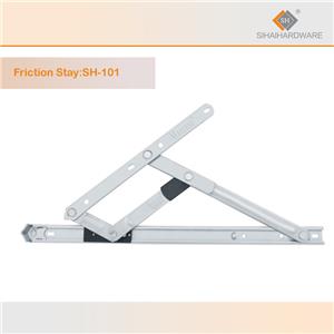
The Triangulation Principle
The fundamental principle behind every Corner Brace is triangulation—the geometric property making a triangle the only inherently stable polygon. A right-angled joint with a single fastener forms a pin connection that rotates freely under load, offering virtually no resistance to racking. Introducing a Corner Brace creates a triangular load path that transforms this unstable mechanism into a stable structural system. The hypotenuse carries compressive or tensile force resisting joint rotation. Brace length, angle, and cross-section determine effectiveness. A 45-degree orientation provides balanced stiffness in both axes, though specific applications may demand adjusted angles for dominant load directions. The brace's second moment of area must resist buckling under compression—a consideration growing critical as length increases relative to cross-section. In window applications where the brace must fit within narrow profile channels, geometric constraints often dictate higher-strength materials.

Material Selection
The material of a Corner Brace fundamentally determines capacity and durability. Steel Corner Braces offer high strength-to-volume ratios with yield strengths from 250 MPa for mild steel to over 600 MPa for alloy grades. Stainless steel—grade 304 for general exterior use, grade 316 for marine environments—provides corrosion resistance without protective coatings. In aluminum window fabrication, Corner Braces are typically extruded from 6063-T5 or 6061-T6 alloys, offering galvanic compatibility with aluminum framing. The elastic modulus directly affects joint stiffness; aluminum's 69 GPa versus steel's 200 GPa means aluminum braces require proportionally larger cross-sections. Where both high stiffness and compact geometry are needed, stainless steel braces are increasingly specified despite higher cost.
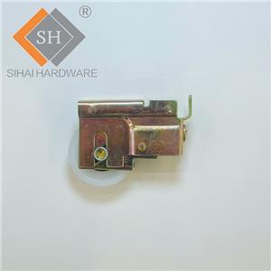
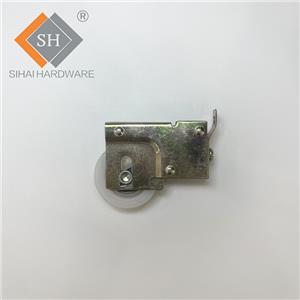
Load Path and Force Resolution
The Corner Brace transmits forces through a precisely defined load path. Under lateral loading—wind pressure, seismic acceleration, or impact—a racking moment develops at the corner joint. The Corner Brace resists this through an axial force couple with the fasteners, developing tension on one edge and compression on the opposite. Stress magnitude depends on brace geometry, applied moment, and the lever arm from brace width. The connection represents the most critical link. Fasteners must transfer brace force into the parent material while resisting the eccentric moment arising when the brace force line does not pass through the fastener group centroid. Eccentrically loaded groups experience combined shear and tension, with outer fasteners carrying disproportionately higher loads—a phenomenon requiring explicit calculation to prevent progressive failure initiating from the most heavily loaded position.
Fastener Engineering
Connection effectiveness governs overall Corner Brace performance. In timber, structural screws with proprietary thread geometries have superseded traditional fasteners due to superior withdrawal resistance. The European Yield Model, codified in Eurocode 5, provides systematic capacity prediction for dowel-type connections, accounting for bending strength, embedment, and thread withdrawal effects. For steel connections, preloaded high-strength bolts create slip-critical joints maintaining rigidity under cyclic loads, while properly designed fillet welds provide continuous load paths. In aluminum framing, self-tapping screws with corrosion-resistant coatings offer anchorage without through-bolting that would compromise thermal breaks. Fastener quantity must develop the full brace capacity; a brace capable of 10 kilonewtons axial load is ineffective if its fasteners transfer only 4 kilonewtons.
Buckling Analysis
For compression-loaded Corner Brace elements, buckling represents the governing limit state. A slender brace may fail by flexural buckling well before material yield. Euler buckling load—inversely proportional to squared effective length, directly proportional to flexural rigidity—provides the framework. Real braces deviate from ideal conditions due to eccentric loading, initial imperfections, and residual stresses. Design standards address this through column curves relating slenderness ratio to buckling reduction factors. For steel window framing braces, a slenderness ratio below 80 is typically required for full yield strength. Where constraints demand slender profiles, designers may specify higher-strength materials or introduce intermediate lateral restraints to reduce effective length.