ARTICLE NO.127 | Crescent Lock: Design Principles, Stress Distribution, and Failure Prevention in Casement Window Locking Systems
ARTICLE NO.127 | Crescent Lock: Design Principles, Stress Distribution, and Failure Prevention in Casement Window Locking Systems
The crescent lock is one of the most widely used locking mechanisms in casement and sliding window systems, yet its apparent simplicity often obscures the sophisticated engineering that governs its performance. Named for its distinctive curved or semi-circular-shaped locking cam, the crescent lock functions by rotating a crescent-shaped tongue or cam from the sash-mounted housing into a corresponding keeper or strike plate mounted on the opposing frame or sash. This rotational motion converts a small manual input force into substantial clamping action, drawing the two mating surfaces tightly together to create a weathertight seal. However, beneath this straightforward operation lies a complex interplay of geometry, material science, and tribology that determines whether a crescent lock will perform reliably over decades of daily use or fail prematurely, compromising both security and weather integrity.
Geometric Optimization of the Crescent Cam Profile
The heart of any crescent lock is the cam profile itself. Unlike a simple hook or bolt, the crescent cam employs a spiral or involute curve geometry. As the handle is rotated, the distance from the cam's pivot center to its point of contact with the keeper gradually increases. This increasing radius generates a wedging or camming action that multiplies the input torque into a significantly higher clamping force. The precise mathematical curve used—whether an Archimedean spiral, a logarithmic spiral, or a custom compound curve—determines the mechanical advantage profile throughout the rotation. An optimally designed crescent lock cam provides low initial resistance during the first portion of handle rotation, allowing the user to engage the keeper easily, followed by a rapid increase in clamping force during the final degrees of rotation as the seal is compressed. Poorly designed cams with linear or circular profiles often fail to generate sufficient sealing pressure, resulting in air and water infiltration at the meeting stiles.

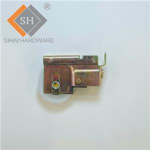
crescent lock
Kinematic Analysis of Lock Engagement
The engagement sequence of a crescent lock involves a multi-stage kinematic process. In the first stage, the cam tip enters the keeper mouth. At this point, the geometry must provide generous lead-in clearance to accommodate manufacturing tolerances and sash misalignment due to thermal expansion or settlement. The second stage involves initial contact between the cam flank and the keeper bearing surface. Here, the contact angle relative to the direction of sash travel determines whether the mechanism will draw the sash inward smoothly or bind against the keeper edge. The optimal contact angle for a crescent lock typically falls between 15 and 25 degrees relative to the perpendicular of the sash closing direction. Angles steeper than this risk excessive friction and galling, while shallower angles fail to generate sufficient draw-in force. The final stage is the fully locked position, where the cam reaches an over-center or self-locking condition. In this position, the line of reactive force from the keeper passes behind the cam pivot axis, creating a mechanical detent that prevents the crescent lock from loosening under vibration or cyclic wind loading—a critical safety feature that distinguishes high-quality designs from budget alternatives.
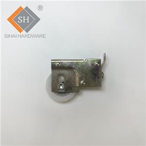
crescent lock
Stress Distribution and Material Considerations
The crescent lock assembly is subjected to complex stress states during both locking and service conditions. When the window is closed and locked, the cam and keeper experience combined compressive, shear, and bending stresses. Finite element analysis of a typical crescent lock reveals that peak stress concentrations occur not at the cam tip, as might be intuitively expected, but at the root of the cam where it transitions into the handle spindle. This is the location where bending moments from the clamping force combine with torsional stresses from handle actuation. For die-cast zinc alloy crescent lock components, which are common in residential applications, the presence of porosity in this critical transition zone can reduce fatigue strength by up to 40 percent. Premium crescent lock designs address this through hot-chamber die-casting processes with precisely controlled solidification rates, minimizing internal voids. For commercial and heavy-duty applications, stainless steel investment-cast cams offer superior fatigue resistance and corrosion performance, though at higher manufacturing cost.
The keeper component of a crescent lock also warrants careful material selection. As the stationary element, the keeper must withstand repeated impact and sliding contact from the rotating cam without deforming. Brass and bronze keepers offer excellent wear characteristics due to their self-lubricating properties, while hardened steel keepers provide maximum resistance to forced entry. The galvanic compatibility between the cam and keeper materials is another critical consideration, particularly in coastal environments where dissimilar metal corrosion can rapidly degrade a crescent lock assembly.
crescent lock
Tribological Challenges and Wear Mitigation
The sliding contact between the crescent cam and the keeper represents a classic tribological system operating under boundary lubrication conditions. Each lock-unlock cycle involves a period of low-speed, high-pressure sliding contact. Without adequate surface engineering, adhesive wear can initiate at the asperity contacts between the cam and keeper surfaces, leading to material transfer, increased surface roughness, and ultimately, galling that makes the crescent lock difficult or impossible to operate. Electroplated coatings such as nickel-chrome or zinc-nickel alloy provide moderate wear protection while also enhancing corrosion resistance. Advanced crescent lock designs incorporate solid lubricant coatings such as PTFE-impregnated electroless nickel or molybdenum disulfide dry film lubricants, which maintain a low coefficient of friction throughout the design life without requiring periodic re-lubrication by the end user.
Common Failure Modes and Root Cause Analysis
Field failure analysis of crescent lock assemblies reveals several recurrent failure patterns. Fastener loosening is the most prevalent issue, occurring when the mounting screws securing the cam housing or keeper to the window profiles gradually back out under cyclic loading. This loosening alters the engagement geometry, leading to incomplete locking or cam-keeper interference. The root cause is often insufficient thread engagement in the relatively thin walls of aluminum or uPVC window profiles. Proper crescent lock installation requires either threaded inserts, thread-forming screws designed for plastics, or rivet nuts in aluminum sections to provide durable anchorage.
Cam fracture is a less common but more serious failure mode, typically resulting from material defects as described above or from forced entry attempts. A fractured crescent lock cam completely disables the locking function, leaving the window vulnerable. Handle spindle shear is a related failure mode that occurs when excessive torque is applied to a locked or jammed mechanism, often by users attempting to force a misaligned window closed. Incorporating a torque-limiting feature or a visible misalignment indicator in the crescent lock design can prevent this type of damage.
Spring fatigue in the detent mechanism represents a third failure category. Many crescent lock designs include a small leaf or coil spring that provides tactile feedback and maintains the handle in the locked or unlocked position. After thousands of cycles, this spring can lose tension or fracture, resulting in a loose handle that no longer provides positive positioning. While not a security failure per se, this condition often leads to user uncertainty about whether the crescent lock is properly engaged.
crescent lock
Applications and Selection Criteria
Selecting the appropriate crescent lock requires matching the hardware to the window type, material, and performance requirements. For aluminum casement windows in residential settings, a standard die-cast zinc crescent lock with nickel-chrome plating provides adequate corrosion protection and smooth operation at an economical cost. For vinyl or uPVC sliding windows, the crescent lock must incorporate a sweep-style cam that accommodates the wider gap between sash and frame, and the mounting screws must be specifically designed for plastic substrate engagement. In coastal or industrial environments, a crescent lock manufactured entirely from 316 stainless steel offers maximum resistance to pitting and crevice corrosion. For wood-framed casement windows, a traditional solid brass crescent lock with a polished and lacquered finish provides both mechanical reliability and aesthetic warmth that complements the timber material.
Conclusion
The crescent lock represents a deceptively sophisticated piece of window hardware whose performance depends on the precise interplay of cam geometry, material science, and tribological engineering. Its spiral cam profile must be mathematically optimized to balance ease of operation with sealing pressure, while its materials and surface treatments must withstand years of cyclic loading, environmental exposure, and sliding wear. Understanding these design principles and potential failure modes—from stress concentrations at the cam root to galvanic corrosion at the cam-keeper interface—enables informed specification and proper installation. A well-engineered crescent lock does more than simply secure a window; it maintains the compression of weather seals, resists forced entry, and provides the user with confident tactile feedback confirming that their window is properly closed and locked.